
Pump System Analyzer
TDH:
Req. Power:
Pump Type:
Daily Energy:
TECHNICAL DOCUMENTATION V1.2
Wastewater Pump Analysis Tool
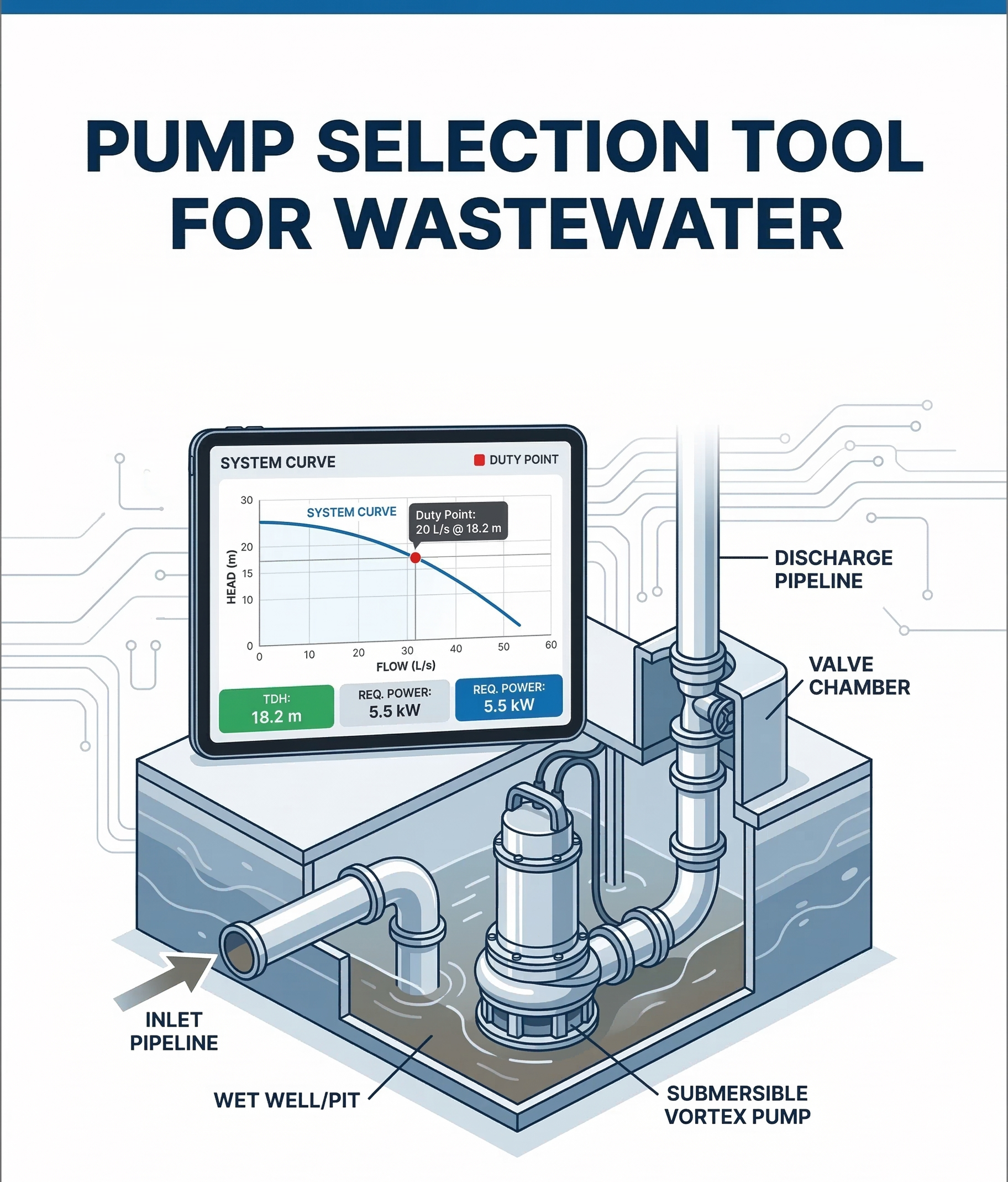
This application is a specialized hydraulic calculation engine designed for civil and environmental engineers to perform preliminary pump sizing and system curve analysis for wastewater lift stations.1. Executive Summary
The tool automates the calculation of Total Dynamic Head (TDH) by integrating static requirements with dynamic friction losses. It provides a visual representation of the system curve and generates professional-grade PDF reports for site submittals.2. Technical Specifications
2.1 Software Architecture
- Frontend: HTML5 / CSS3 (Grid & Flexbox).
- Logic Engine: Vanilla JavaScript (ES6+).
- Visualizations: Chart.js (Canvas-based rendering).
- Export Module: jsPDF (Client-side PDF generation).
2.2 Hydraulic Methodology
The core engine utilizes the Hazen-Williams Equation for calculating friction head loss ($h_f$). This method is preferred in wastewater applications for its reliability with smooth-walled pipes (PVC, HDPE, Ductile Iron).The governing equation used is:$$h_f = \frac{10.67 \cdot L \cdot Q^{1.85}}{C^{1.85} \cdot d^{4.87}}$$
| Parameter | Description | Default Unit |
|---|---|---|
| $Q$ | Volumetric Flow Rate | L/s (converted to $m^3/s$ for calc) |
| $d$ | Internal Pipe Diameter | mm (converted to $m$ for calc) |
| $C$ | Friction Coefficient | 140 (Standard for Plastic Pipes) |
| $L$ | Total Equivalent Length | Meters |
3. Functionality Description
3.1 Input Module
Users provide six critical data points. The app includes a “Project Name” field to ensure data traceability in generated reports.3.2 System Curve Generation
The app dynamically generates a 10-point system curve. By iterating through flow rates from $0$ to $150\%$ of the target flow, the tool plots the relationship between demand and resistance, allowing engineers to identify the optimal Duty Point.3.3 Automated Pump Classification
The suggestion engine uses a logic matrix based on the Specific Speed and Head-to-Flow ratios:- Grinder Pump: Triggered when Flow < 8 L/s and TDH > 30m.
- Non-Clog Centrifugal: Triggered for high-volume flows (> 40 L/s).
- Vortex/Effluent: Default for standard low-to-mid range applications.
4. Engineering Assumptions & Safety
- Motor Power: Calculated using
P = (ρ * g * Q * H) / η. - Efficiency (η): Assumed at 65% (Standard for wastewater submersibles).
- Safety Factor: A 20% “Nameplate Safety Margin” is automatically added to the required kW to account for fluid density variations and motor startup torque.